SRLL(Simple Radio Link Layer)
<Introduction>
CUTE-I of Titech is using AX.25 protocol, which is majorly use by amature
radio to communicate with the Ground Station.
Other than that, CUTE-I is using original protocol experimentaly, which
have developed at Titech called SRLL(Simple Radio Link Layer).
Å@
<Sequence of Development>
As known, AX.25 protocol is developed to make Packet communication by
amature radio technology. This AX.25 protocol features function to send
and receive variable binary data. AX.25 have developed under assumption
of garanteed communication line such as telephone line. Therefore, with
one bit of error in any frame will crash the frame totally and the date
will not be transmitted under AX.25. Compared to telephone line, radio
line can not afford high quality and stabilized communication, which
will cause much more error than telephone line. Thus, Mr. Funada developed
SRLL protocol to cancel the error and correct it to the original data.
Å@
<Structure>
Based on result of PRUG96 project, by elinimating HDLC, which is incompatible
with error correction code, and use frame detection and error correction
code, it will be possible to make communication under low quality line,
such as radio communication line. Concretely, SRLL will use following
system which had been adopted by PRUG96 Project:
* Fixed length packet(by fixing the packet length, it will be possible
to prevent error on frame detection cause by bit flipping)
* Frame detection by 32bit PN code
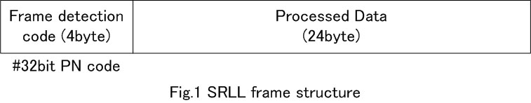
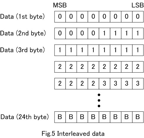
Fig.1 will show the structure of SRLL frame. SRLL frame is composed by frame head detector(32bit PN code), and 24bytes fixed length fo sending data bit. This 24bytes includes main data(user data), error correction code, and check sum.
Å@
<Generation
of error correction code and submitting data>
Fig.2 shows sequence of SRLL protocol frame generation.
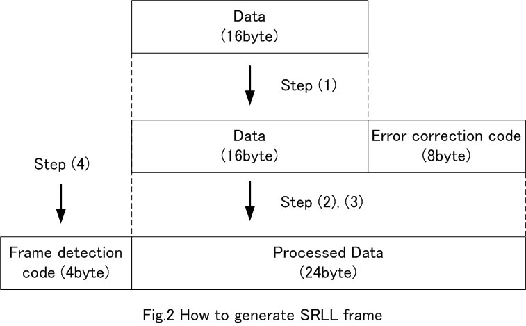
Step1.
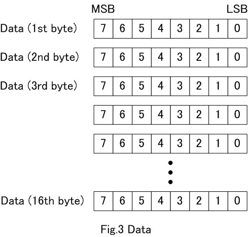
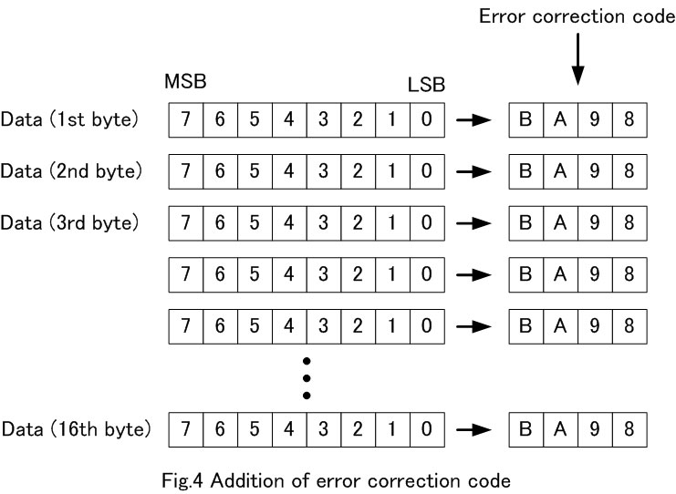
Based on Huming code, SRLL will first generate error correction bit line(8byte)
from user data.(From Fig.3 to Fig.4)
Step2.
To the generated(addition of user data and correction code = 24byte),
SRLL system will do interleave operation.(Fig.5)
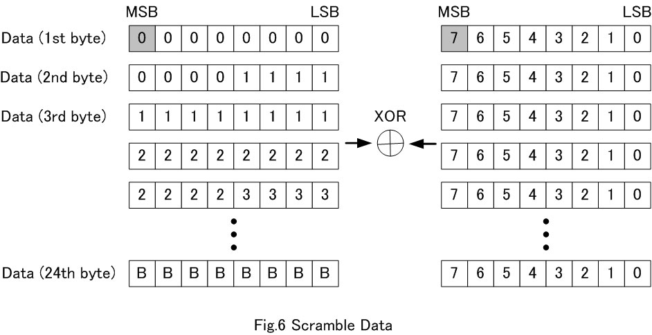
Step3.
For next step SRLL system will eliminate DC elements and repeating elements,
and to average the distribution of electro wave, SRLL will filter scramble
pattern.(Fig.6)
Step4.
For last step, SRLL will add frame 4byte of detection code to the frame,
thus one frame will be sent as 28byte of data.
Å@
Å@
Å@
<Receiving
and correction code analsis>
For each clock, it will input received data to 32bit shift registor and
check whether it matchs with 4byte of frame ditection code. In our mission,
the program accept 3bit of error in data and recognize as matched data.
Once it is recognized as coincident data, the program will store the rest
of 192bit in to a data row as a from of 24byte data. Sending data will
be acquired by operating opposite process(releasing scramble and interleave
control) to this data row. It is possible to detect 2bit error and possible
to correct 1bit error.
Å@
More information
about SRLL protocol is shown web site as follows;
Error correction code and scramble parameter
TNC circuit diagram for Receiver
Å@