 |
 |
 Experimental Overview
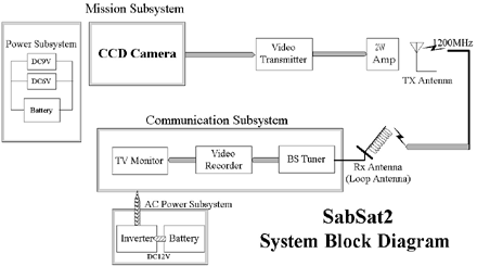
CanSat transmites CCD image to the ground station using high power amplifier. On the GS side, pointing GS antenna to the CanSat direction measuring AGC level, and receiving CCD image certainly.  Experimental Objective
Downlink Engineering Test Downlink images acquired from a CCD Camera to the ground station When we receive a radio wave from CanSat with directional antenna at GS, we try to point GS antenna toward CanSat by utilizing AGC level.  Exwerimental Signification
Operating this ARLISS experiment, we make a basic study of micro/pico satellite, Communication technology, pointing control of antenna technology, and this experiment is applicable to CubeSat project.  CanSat#004 "SabSat2" System Block Diagram
 CanSat#004 "SabSat2" Experimental Sequence
1. CanSat release from the carrier is detected by micro switch, after that pwoer of CanSat is ON 2. CanSat start to transmit CCD image, on the GS side, start to receive CCD image and record it. 3. On the GS, the antenna is pointed to the CanSat direction measuring a AGC level of received radio wave. 4. Receiving CCD image certainly and continuously to the CanSat landing. 5. Recover the CanSat.  For More Information
§ SRTL Director Prof. Saburo MATUNAGA< Matunaga.Saburo@horse.mes.titech.ac.jp> § SRTL ARLISS 2000 CANSAT TEAM Student Director Koji NAKAYA< koji@horse.mes.titech.ac.jp> § CANSAT#004 "SabSat2" Project Manager Hirotaka SAWADA< hiro@horse.mes.titech.ac.jp> |
|
|
 |
Copyright(C)
1999,2000,2001 -CANSAT 4 SabSat2- All rights reserved. Tokyo Institute of Technology Space Robotics and Teleoperations Laboratory (SRTL) ARLISS 2000 CANSAT TEAM Contact : Hirotaka SAWADA |