TOP ![]() News
News![]() Results for Cute-1.7 + APD
Results for Cute-1.7 + APD
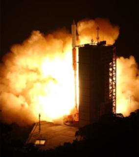
The first version of our satellite was launched by the JAXA/ISAS M-V#8 Rocket as a subpayload, the main payload being the JAXA “ASTRO-F AKARI" satellite.
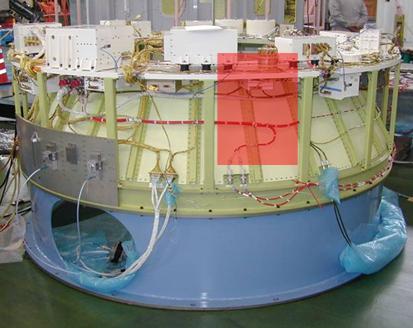
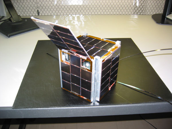
CUTE-1.7 + APD was launched on February 22nd 2006. It was mounted, with its separation mechanism shown on Fig.1, in the B3-PL unit of the rocket.
Several technical issues, going from recurrent IC failures in the communication subsystem to unfulfilled power consumption needs, led our team to put aside some of the planned mission and focus on analysing the satellite’s current and retrieving the available data.
Cute-1.7 + APD stopped accepting any upload command in the evening March 16th when passing over Tokyo, and now the satellite is not under control. Because the operation was conducted completely without error, it was possible that some trouble occurred with the satellite on orbit. While rescue operations, it was confirmed that the command processing system stopped operation by some cause while normal operation of the command receiver is verified. So, it is considered that the command processing controller may have been damaged by radiation.
The team reached to the conclusion with the highest possibility of damage by the radiation.
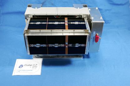
Cute-1.7+APD was developed directly adopting the COTS devices such as PDA, as a concept in order to achieve a low-cost, short term development of satellite. PDA operation on the orbit could be confirmed, and a part of the objectives of the satellite was achieved.
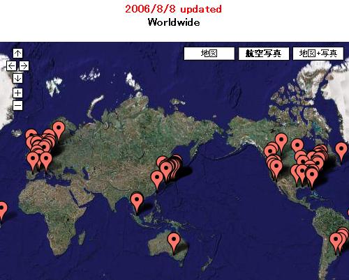
Moreover, as CubeSat in Japan, Cute-1.7 + APD has communication system for the first time by the GMSK modulation method, and got the reception report from amateur radio operators’ all over Japan. It will be expected that a lot of satellites use this modulation method in the future.
In the science module, basic operation was confirmed including the circuit around the APD sensor.
It was not possible to conduct attitude control experiment though the attitude control system installed 3-axes active controller for the first time as CubeSat in Japan, and scheduled to be conducted.
Gyroscopes and sun sensor were confirmed to be in normal operation.
At present, Cute-1.7 + APD is transmitting a continuous wave that is not modulated.
The restoration operation will be continued in the future though the orbit life in the calculation is 1 or 2 year.
Moreover, the problems in Cute-1.7+APD are thoroughly investigated and the satellite of the second improvement type is developed in order to achieve the missions of this 1st one. The project team aims at the launch in the next year.
The tether deployment mission was not conducted. It has been found not to be able to achieve the mission objective because there was some incompleteness in the proposed structure. It has been decided not to install this mechanism in the Cute-1.7 + APD#2.
To deal with damage related to the radiation, the following function is installed in Cute-1.7 + APD#1.
For Soft Error (SEU)
For Hard Error (SEL)
For power supply interception function not to work while normal operation which uses the large current device such as PDA, the current threshold that the current watch circuit works was set to a high value, about 4 amperes.
This function doesn't operate correctly when a current increase by the hard error is less than 4 amperes.
The irradiation test was conducted for only PDA. Microcomputer seemed to be tolerant for success of CUTE-I, but the situation implied the possible SEL in the microcomputer onboard.
The irradiation examination was conducted again whether or not the current increase by the microcomputer’s hard error exceeds the threshold at the Research Centre for Nuclear Physics of Osaka University.
It aimed to examine these radiation resistances by applying proton beam to H8S-2328F microcomputer that the communication system was using. Energy of the radiation is set to about 55MeV.
Fig.4 shows the current history of the H8 microcomputer while the examination. When SEL occurred and the overcurrent flows, the power supply is cut off, and it is confirmed to automatically recover by that function, which is a result of the overcurrent watch circuit’s normal operation. When H8 microcomputer of Flash ROM is adopted for the flight model, it should be considered to take SEL measures enough.

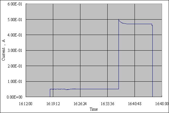
The experiment that was done without allowing power supply interception by removing power supply interception function was conducted. This means that if SEL occurred, the current is not cut off, and we can measure the current increase while SEL. Fig.5 shows the result. When SEL occurred, the current of 500mA was consumed in H8/2328 though the current of about 50mA flows when it is in normal. Therefore, it was confirmed that ten times of the current in normal operation flow in the maximum when SEL occurred in the microcomputer.
However the current increase is even much smaller than the power supply cut off function works correctly. As for Cute-1.7 + APD#1, over current intercept function could not be expected to work because of much higher threshold level than the increased level of electric current consumption of microcomputer. Higher threshold was set because the current at only one point of EPS source was observed in the satellite. Then, it is necessary to measure the over current for each microcomputer in the next satellite.
As a result, it was confirmed that the restoration function did not operate correctly when it was confirmed that a current increase did not satisfy the threshold of the current watch circuit.

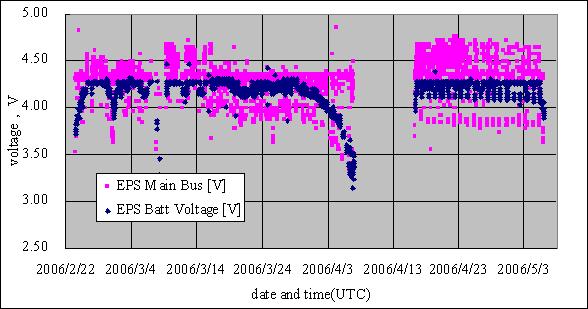
It was confirmed that the current consumption temporarily increase from the change of the battery voltage recorded and downloaded since March 16th though the telemetry transmission was normally operated for a while after the command analysis system stopped operating.
Let’s have a look at the House-keeping data.
Telemetry disappears once at the evening, April 7. The voltage of the battery has decreased gradually since about one week before, and it was possible that the voltage descent below the operation voltage of the Telemetry transmission system.
The satellite orbit went in eclipse for the first time on April 15, and it was possible that all satellite electric power shutdown and the hard error was cancelled. Then telemetry revived on April 16.
The voltage of the battery rose again, and over consumption of the current went out.
Telemetry disappeared completely on May 6, morning. A rapid decrease of the battery voltage was confirmed in the evening, May 5, and over consumption of the current was confirmed again. All satellite function was lost rapidly the day before.
The increase and decrease of current consumption can be explained by the effect of the radiation damage.
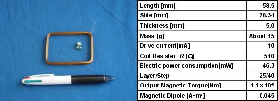
A magnetic torquer system, shown in Fig.9, was developed. Simulations were also conducted to model the damping when using the magnetic torquers with a B-dot algorithm. The results are obtained when taking ω = (0, -0.1047, 0) [rad/s] as initial angular velocity. Taking into account that Cute-1.7 + APD uses sampled data for the algorithm, this simulation showed it would take about one and a half hour to effectively damp the satellite as planned.
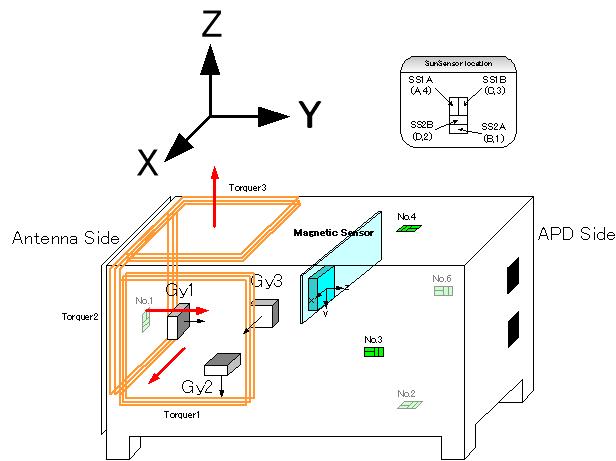
The satellite’s attitude determination system is composed of a three-axis gyro sensor, a three-axis magnetometer, and sun sensors. The gyro sensor is a combination of three ADXRS gyroscopes from Analog Devices. The magnetometer is a Honeywell HMR2300. The sun sensors consist of simple photodiode arrays (S6560 from Hamamatsu Photonics) fixed on the walls of the satellite structure. The satellite posseses two attitude determination methods in his system, a geometrical method, and a request based method.
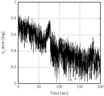
Simulation results for the geometrical method, considering ω = (0.1 -0.1 0.5) as the initial angular velocity in [rad/s], are shown in Fig.10.
Conversion into the USB data is needed so that the magnetic sensor output data by serial communications. The operation of the conversion circuit was unstable, and debugging was not able to be completed before launch of the satellite. Therefore, operation decided to be stopped with software though the magnetic sensor was actually installed. Therefore, the data of the magnetic field was not able to be acquired.
Serial to/from USB conversion circuit is the one that was developed by the team from the circuit design to the driver development. There was a variable for the reasons of having developed independent though a detailed cause was not understood. There was such a problem though it thought development to become easy because PDA connected the USB device, too.
Below is data effectively retrieved on 7th March from Cute1.7 + APD’s gyroscope. Fig.11(a) shows the angular velocity whereas Fig.11(b) shows the quaternion computed from this data.
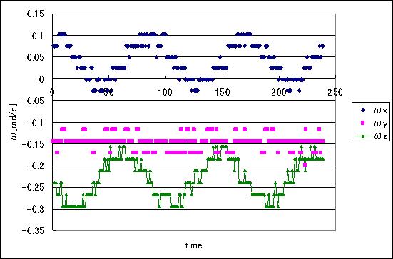
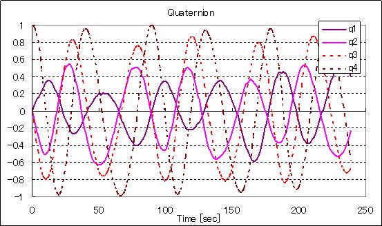
We can see that the rotation about the z axis is the largest. The moment of inertia along this axis is thus the largest, and the average angular velocity is of 0.28[rad/s], Cute-1.7 + APD thus being rotating at a rate approaching one revolution every 22.5[s]
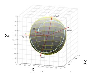
The data of the Sun sensor acquired on February 27 is shown in Fig.20. The coordinate system is body fixed coordinate system that is shown in Fig.16, and Fig.20 is seen from roughly the same angle as Fig.16. Red vectors indicate direction of the sun in body fixed coordinate. According to the data from the sun sensor, it is confirmed to rotate about the X axis at this moment. The cycle of the rotation is about 30 seconds. Because the rotation axis by the gyroscope data was Z axis, it is almost the same tendencies of rotation about the major axis in the principal axes frame.
The attitude determination and control system that can be installed in micro satellite was developed, and the examination was conducted on orbit. The data of the gyro sensor and the sun sensor was able to be acquired. However the acquisition of magnetic sensor data, attitude control experiment and attitude determination experiment was not able to be conducted.
OSCAR is an acronym for Orbital Satellite Carrying Amateur Radio. OSCAR series satellites use amateur radio frequencies to communicate with earth. Putting “OSCAR (Oscar)" in a part of the name of the satellite and applying the sequence number is a custom. An original name “RS-xx title" having been used for the amateur satellite launched in a Soviet age (RS is abbreviation of Radio Sputnik) also uses the name of AMSAT-OSCAR-21 at RS-14. According to the rule that IARU and AMSAT-NA provided, the name and the sequential number for “Oscar" are issued by AMSAT-NA, for satellites which are confirmed to work on orbit and to be operated.
"Oscar" is not necessarily limited to “Handmade of the amateur". The UoSAT series is an example of this, which is satellite developed by the University of Surrey.
While over 60 research groups of universities and space agencies in the world carry out research and development of very small satellites, many of them have not realized the launch. Tokyo Tech, operating two satellites of different systems, has achieved a milestone in development of space technology. By the reason why the group’s pioneering work will certainly inspire others to follow them in constructing and launching this very innovative type of spacecraft, AMSAT-NA issued the two amateur satellites, “CUTE-I" and “Cute-1.7 + APD", developed by our group with the designation of CUBESAT-OSCAR numbers.
CUBESAT-OSCAR-55(CO-55) was issued to CUTE-I, which is the first number of named “CUBASAT-OSCAR" series, and CUBESAT-OSCAR-56(CO-56) was issued to Cute-1.7+APD.
The two satellites were admitted worldwide as amateur satellites, and could able to be joined to amateur radio satellites.
The successful launch of Cute-1.7+APD enabled us to validate our design methodology and detect the weak points in the hardware system we had set up. The second launch, scheduled at the end of 2006, gives us the opportunity to fix and improve Cute-1.7 + APD’s design in order to fulfill all the missions planned. The experience acquired with Cute-1.7 + APD#1 has given us the knowledge and know-how to quickly develop a fully functional - enhanced version of this satellite. Thanks to our cost-time efficient design methodology, our first results were quickly taken into account and the new satellite is being developed in a minimum amount of time, enabling us to focus on the missions and objectives. We now look forward providing the scientific and amateur communities with our next results and public on-orbit amateur radio-services.
The team aims at the Cute-1.7 + APD#2 launched in 2007. The followings are to be improved.
Copyright ©, Tokyo Institute of Technology, All Rights Reserved.
![]()
![]()
![]()